Sidebar

Home


Knowledge Base


Guides & Tutorials

Projects

Samples

kb:tutorials:basic:how_to_configure_and_use_tool_table

How to configure and use tool table

Tool table is like a digital playbook for a CNC machine. It's a list or database that contains information about the various tools that can be used with the CNC machine. Each entry in the table includes details such as the tool's number, name, type, offsets, cutting speeds, and other parameters.

Note that the tool table is not an essential feature, and there's nothing to be afraid of; instead, view it as a handy feature. Its main task is to assign a tool name next to a tool number.

Adding tool to tool table

To access tool table click Machine/Tools/Edit Tool Table:


As mentioned earlier, consider the tool table as a repository of tools that your machine can employ for its daily machining tasks. To illustrate, let's take the example of an endmill tool, a commonly used tool that you'd like to designate as tool number 1.

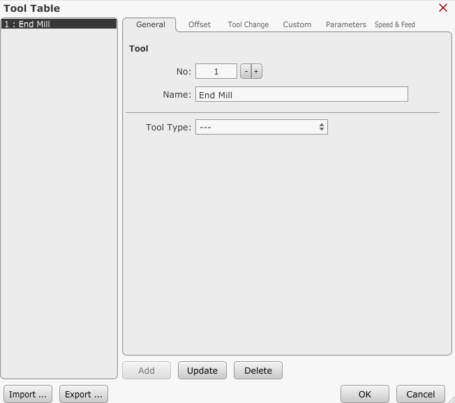
Simply open the tool table, input tool number 1, label it as 'End Mill,' and then click the 'Add' button:


Tool number 1 with a name “End Mill” is now successfully added to the tool table:


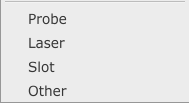
There is a high chance that the tool type you want to add to tool table already exist in the TNG library. Click the tool type drop down button and select suitable tool type option from the drop down menu:

Beside normal tool types (mill, drill, centre drill…) user can also choose between Laser, Probe, Slot and Other as tool type. These four options are used when as tool, unconventional devices are used(laser module, probing device…).


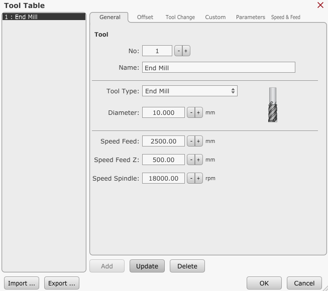
Once tool type is selected, additional tool parameters will appear, such as: Tool diameter, Speed Feed, Speed Feed Z and Spindle speed.

Each tool can have these parameters filled, as per its technical data.

To confirm and update tool profile, click the Update button.

Parameters associated with tool's type do not directly impact the TNG or the tool change process. Their significance lies solely in the calculations performed by the integrated calculator at the Speed&Feed tab. However, we'll delve into that aspect later on.


Each tool can get assigned many additional parameters located under tabs: Offset, Tool Change, Custom and Parameters.

Offset tab

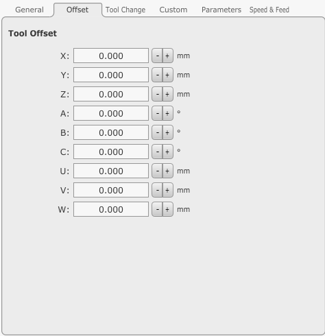
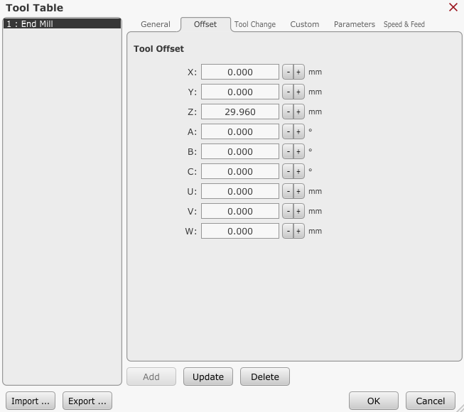
ATC is usually mechanical concept related to where the machine keeps its tools and how it accesses them, like on a tool rack, carousel, or conveyor system. For machines with ATC, this tab stores tool offset values in advance. Typically only Z axis offset is stored, but in a case of tool type such a laser, X and Y axis offset would make sense.

You can skip this tab if your machine doesn't have an ATC (automatic tool change) system. For any other tool change system, tool offset is usually measured after each tool change.


For example, with ATC, result of tool length measurement for Tool nr.1 - End Mill would be stored like such:

Tool Change tab

Tool change Position

With ATC, each tool has its own unique position, and this is where position coordinate values are stored. But more about this in the ATC tutorial.

Skip Tool Change & Skip Tool Measure

Certain tools, like probes and laser modules, require distinct handling during tool changes. This stems from factors such as their specific use and geometry. Probes, being delicate and costly devices, demand special care to prevent damage during routine tool changes. On the other hand, lasers, typically fixed in position, don't undergo the standard tool change process. For both such cases, option “Skip Tool Change” can be used.

The concept of “Skip Tool Measure” aligns with this philosophy. If a tool is a laser, there's no need for measurement. This principle extends to all tools when an Automatic Tool Changer (ATC) is employed, as all tools are pre-measured for efficiency.

Sensor Offset

Certain tools, like fly cutters or annular cutters, have a different shape where the farthest tip isn't at the center. This means these tools require measurement using a tool sensor with a slight xy offset.

Custom tab

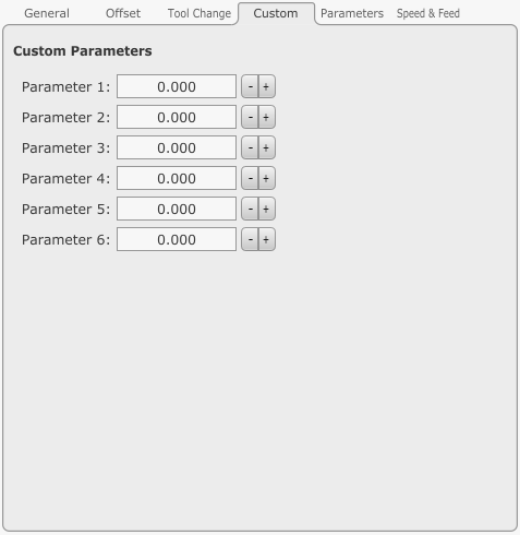
At times, tweaking the M6 script code is necessary. With these parameters, users can create tool change scripts that handle even the trickiest tool change ideas and requirements.

Parameters are:

<_tool_par1_num|tool_num>

<_tool_par2_num|tool_num>

<_tool_par3_num|tool_num>

<_tool_par4_num|tool_num>

<_tool_par5_num|tool_num>

<_tool_par6_num|tool_num>

Parameters tab

Each tool has a designated role in machining, determined by its unique geometry. Optimal performance is achieved at specific feed and spindle speeds for each tool. In this tab, users input the tool's geometry values.

These values aid in the calculation of precise feed and speed values using the calculator found under the Feed & Speed tab.

Since there will be a dedicated tutorial on how to use a calculator, parameters under this tab will be described in detail there.

Feed & Speed tab

Selecting the right feed and speed values for a specific tool can be challenging. Industry solutions like advanced CAM software or standalone calculators are often costly. TNG, however, provides a free calculator that delivers excellent results, catering to the needs of most users. It's worth noting that for expert users engaging in trochoid or adaptive feed machining, more specialized tools may be necessary. As previously mentioned, a comprehensive tutorial dedicated to this calculator will be provided separately.

kb/tutorials/basic/how_to_configure_and_use_tool_table.txt · Last modified: 2023/12/19 20:29 by andrej

Page Tools